We share the mechanical operation of RT10-C hand push rail flaw detection cart, customer can vist the page and get more support to use this device.
The Push Cart on the Ground
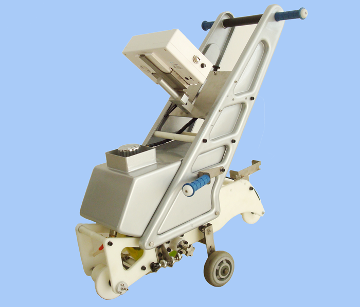
As shown in the above Figure, when the part is not on track for testing, the wheel for walking on the ground is at down position.
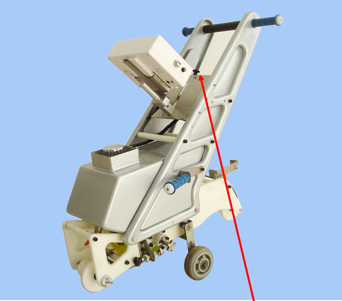
On Track Testing
To put rail flaw detection cart on track for testing, first pull the button in the center of the cart as shown in the following figure, so the ground walking wheel is in the up position. As show in the follwing picture.
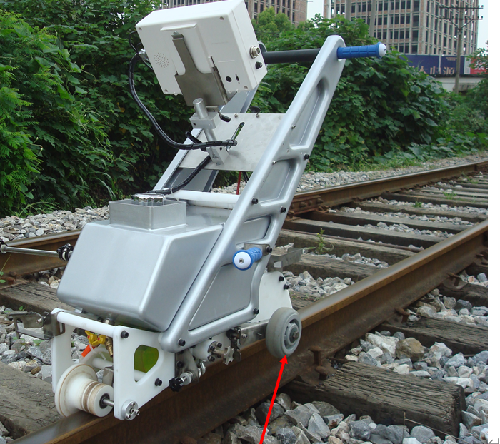
Tilting Adjustment of Hand Push Cart
After the push cart is on the track, one as to adjust the tiling of the cart, so as the base reflection signal is at maximum. To do so, go to single channel A-scan of the instrument and switch to channel 9 (zero degree channel). First decrease the gain so as the signal is not full scale. Use the two buttons on the cart to move the motors, so as to make the adjustment of the tilting of the push cart. Watch the base reflection signal, when the signal is at maximum, the cart tilting is at the right position.
During the real testing, the rail condition change, it can cause the base reflection signal decrease, one also has to make the adjustment.
Wheel Probe Adjustment
The position of the wheel probe is very well adjusted before shipping. However, for some reason such as wheel probe replacement, the wheel probe position shall adjust again. The red knob in figure is used to adjust the lateral movement of the wheel probe, which makes the wheel probe is in the center of the rail. The black knob is to rotate the axis of the wheel probe, so that it make the sound beam is at right angle of the base.
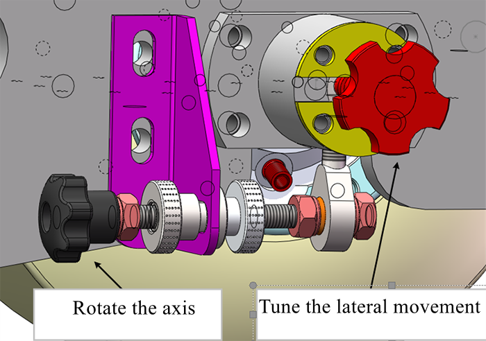
Open the A-scan, and switch to zero degree channel, also decrease the gain so the signal is not full scale. Loosing the bolts, rotate the black knob and watch the base reflection signal. When the signal is at maximum, the sound beam f will be at right angle of the base. Tight the two nuts near the black knob. Then tight the bolts on the other side of the axis of the wheel probe.
To make the wheel probe at the center of the rail, rotate the red knob as shown in above figure. The red knob will make the lateral movement of the wheel probe. One can observe if the wheel probe is in the center of the rail. Once the wheel probe is in the center of the rail, it can tight the bolts on the other end.